Menu

Show posts

This section allows you to view all posts made by this member. Note that you can only see posts made in areas you currently have access to.

Show posts Menu

Messages - gil

#2596
Digital Modes / Re: Winmor, Winlink with my KX3?
January 10, 2013, 02:54:41 PM
QuoteOn the other hand, you can fully expect to arrange with your fellow preppers or other correspondents to send text-only or even small spreadsheet type files via the radio port like we do now with our small group of PREPNET folks, including Tim, Tom and some others.  Works well and would be especially useful for prepping purposes.

That is the whole point yes..

I don't use Windows, so I need to install it fir$t.

Isn't there some kind of automation with the SDR (KX3 is an SDR) going on to find relay stations?

Anybody has an old genuine XP CD for me?

Thanks!

Gil.

#2597
Digital Modes / Winmor, Winlink with my KX3?
January 09, 2013, 06:12:27 PM
So, in plain English, what do I need to send and receive emails with my KX3?

Gil.
#2598
Morse Code / Re: QRP CW has come a long way
January 09, 2013, 04:24:22 PM
What could be used to build a hand crank or bicycle generator?

Gil.
#2599
Morse Code / Re: QRP CW has come a long way
January 08, 2013, 09:22:48 PM
QuoteI gather you like resonant stuff, but have you ever thought of picking up or building Elecraft's little T1 just to have in the kit?

I have thought about it, yes, and will get one some time. My K1 has the auto tuner, and I will get one for the KX3. I do like resonant antennas, just to squeeze a bit more power out, but sometimes, you just can't reduce SWR... Especially when operating near metal structures, using random wires, antennas on bands they are not designed for, or things that are not supposed to be antennas.!

QuoteWhen I think of what an underpowered radio used to weigh (after being militarized), jeebers.

Speaking about militarized, the only thing I don't like about Elecraft products is their lack of weatherproofing... Other than that, I don't think they have competition out there.

Gil.
#2600
Morse Code / Re: QRP CW has come a long way
January 08, 2013, 07:33:43 PM
Excellent story, thank you! Of course they didn't call it QRP back then, I assume, but it has indeed come a long way. The same principles apply however, mainly, portability.

For me, QRP means just that, small, simple and portable, with low current drain. The low power is a consequence of these requirements. So, when people argue about whether 6W is QRP or not, I roll my eyes... It's not so much about the power, although it is very interesting to see what can be done with very little. If there was a pocket size radio that had a 100W output and drew only a couple amps, I'd be the first one to buy it. We can't change the laws of physics, so it isn't going to happen.

The painting is great by the way, I'd love a print for the shack!

Morse code is also the hero here. There was no technology to encrypt voice back then, or data modes, that I know of... It still works as well today.

I just sold my K2 and my Icom IC-271 to buy the Rolls Royce of QRP radios, the Elecraft KX3. It is awesome! Filtering CW down to 50HZ! I'm in QRP heaven. It outputs 12W, but yes, for me, that is still QRP. On the internal batteries, power is 3-5W. It even allows me to send RTTY or PSK31 using the paddles. Decoded text scrolls on the screen. It's 160-6m, and a 2m module is in the works.

Anyway, I will be ordering a book soon: "The Clandestine Radio Operators" by Jean-Louis Perquin.

QRP is a necessity...

Gil.

#2601
Hello Bob,

The problem with epoxy is that it can't be powder coated.
They have nice Hammertone powders perfect for the task..

Gil.
#2602
Excellent, mine is just a small ammo can.. Make sure the front doors are well connected to the body of the cabinet. Chicken wire would not work, holes are too big. I wouldn't use anything like a mesh anyway. The holes have to be smaller than the wavelength of the "distrubance," or something like that... Anyway, there should be no gaps anywhere...

Gil.
#2603
Man I'd like to have a cabin in Idaho! What's the range with the WiFi?

Gil.
#2604
Well, part one was easy... The wiring is pretty bad. Capacitor leads are not even trimmed. The key jack hole has burrs all around. Now I need to either borrow a torch or get someone who knows what they are doing to fill those holes with a TIG welder. The transformer works, but it is very noisy. Hopefully it will quiet down when bolted back on the chassis. With 120VAC in, I see 640VAC out (320VAC at center tap). The other voltage looks like about 21VAC, which I need to look into..

There is a Yahoo group for the AC-1: http://groups.yahoo.com/group/amecoac1/

If anyone knows anything about screen printing on metal cases, please enlight me! Thanks.

Gil.
#2605
After building a K2, I long for some simplicity... And what could be simpler than a vintage 50s tube transmitter? The Ameco AC-1 is a cheap one-tube (plus one rectifier tube) Novice transmitter that was sold as a kit for around $20. These days, they have become rather sought after, and go for more than $300 on Ebay! I found mine for $50, but as you can see on the photo below, there is much work to be done. Someone had the bright idea of drilling a hole for a key plug right through the Ameco logo on the front! I guess back then, nobody expected these transmitters to become collectibles...
There are also two extra holes in the back and there is an SO-239 plug added, which is not original. The antenna plug, I will keep. The key jack hole in the front has to go. So, my step by step plan is:


  • Remove all components and hardware.
  • Weld-fill the hole in the front and two holes in the back.
  • Sand and paint the transformer
  • Sandblast the chassis.
  • Have the chassis nickel plated.
  • Have the chassis powder coated on the outside.
  • Silk-screen the front panel with original print.
  • Mount all the components back in.
  • Call CQ on 7030!

Suggestions and questions are welcome. Stay tuned for more...

Gil.
#2606
Antennas / Re: A magnetic loop antenna for 40/30/20m.
January 07, 2013, 01:57:50 AM
I experimented with a 330pf high voltage capacitor in parallel with the air variable. I can tune the loop on 80m with a 1.1:1 SWR! Good news, but it is very inefficient. Though, Ray heard me, barely, 800 miles away. With 12W in, I am sure the amount radiated is measured in milliWatts... Reception isn't that great either, but hey, it works.

The loop will be painted in the next few days, bright red!

Gil.
#2607
Antennas / A Ladder Line Slim Jim for 6m.
January 07, 2013, 01:48:45 AM
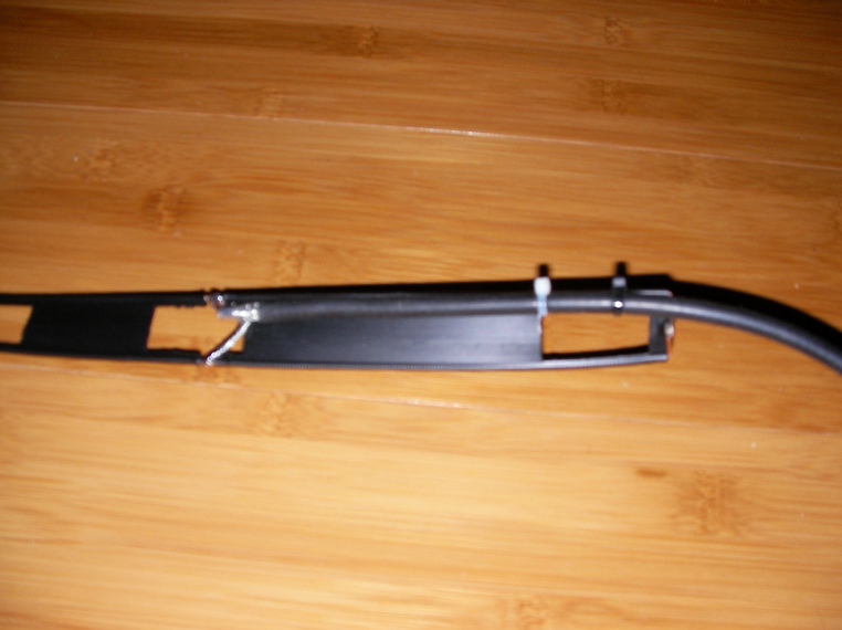
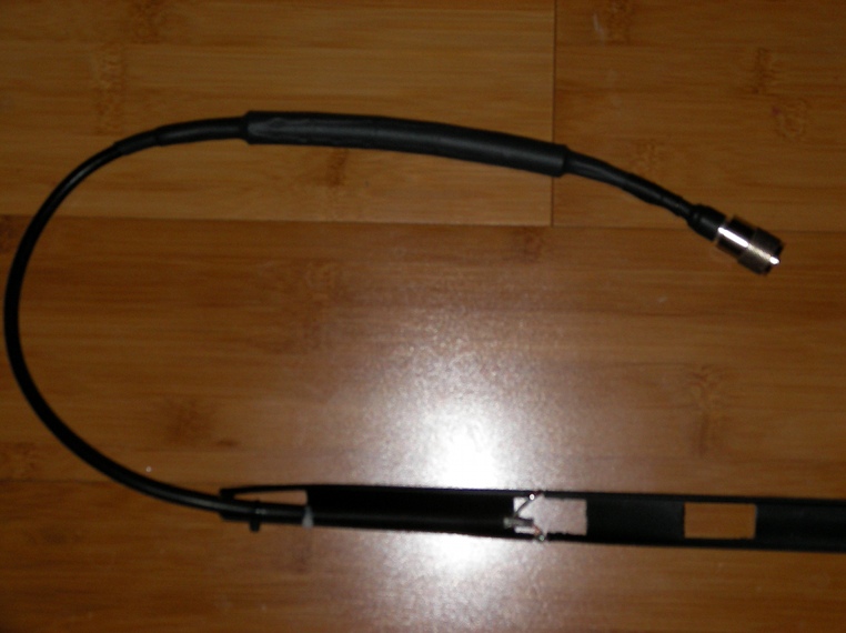
Ah, I forgot to post this one... Completed before my 6m magnetic loop. It is a simple ladder line Slim Jim made of 450 Ohm ladder line (http://thewireman.com #551), solid copper. I wish now I had chosen the multi-strand 16AWG type (#552) because the #551 is very brittle and breaks easily. Not a problem since I mounted the antenna inside a PVC tube, but it would break soon or later if I rolled it up often for portable operations. So, the next one will be more flexible..

The idea came from: http://www.astromag.co.uk/j-pole/
It's really a Slim Jim, not a J-Pole.
Total length of the ladder line is exactly 14ft.
The quarter-wave length side is 54-3/4"
Gap is 3.15" (easier to measure 80mm).
It is fed 5.6" (14.2cm) from the bottom.

The ladder line wires are soldered together at the top and the bottom.
(If you bend the copper 90deg, it will break, solder a piece of wire between the two..).
The 80mm gap is cut without removing the plastic. I slice it, cut the copper and pull the piece out.

Here is how the antenna is fed:


Here with the Palomar Engineers RF choke kit:
(They don't seems to sell the kit anymore, but they have the ferrite beads: http://palomar-engineers.com)


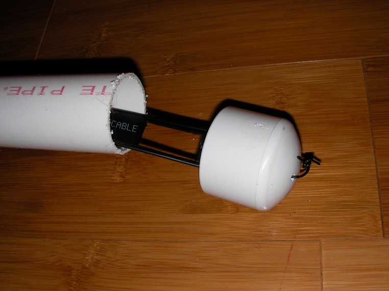
The PVC tube is 10'+4' joined by a coupler and epoxied.

Here is how I attached the ladder line to the top end-cap:


SWR is 1.6:1 on 50.4, and 1.5:1 below that. I get the same SWR on my 2m copper tube Slim Jim... I haven't heard anyone on the air yet, so I can't give an on-air report. I am sure it works just fine. I will definitely make a "roll-up" model for 6m, and another for 2m, to be used with an HT. I have a 25' RG-174 patch cable that I will cut in two to feed them both. Those two antennas will be great with my KX3, and fit in a small pouch. You can make one in 20 minutes without breaking a sweat...

Gil.
#2608
Watch the videos...: http://www.team-blacksheep.com

Gil.
#2609
Antennas / A Magnetic Loop for 6m.
January 03, 2013, 02:50:49 AM
Hello,

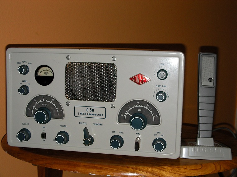
Since my big loop works so well, I decided to build one for 6m. I have a couple working Gonsets (Communicator III & G-50) which are mostly used on 50.4MHz. I haven't heard anyone yet, but i am hoping a 90% efficiency loop will help. Great thing is, it is only 1.4ft. in diameter!

Be warned that magnetic loops are dangerous! Lethal voltages are present on the exposed parts while transmitting, and 6m is the worst wavelength as far as RF exposure goes. DO NOT stay near the loop while transmitting, and DO NOT let anyone get near it!

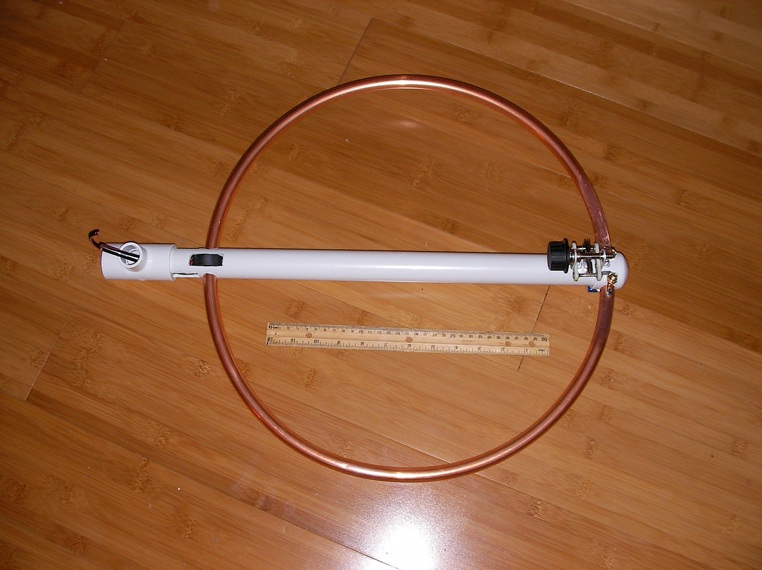
I started with a 3/8" soft copper coil. It came in a 25' long coil, and I have enough left for two 10ft. perimeter loops (more on that later). The length of the copper is 56 inches. My capacitor is a 3-37pf air variable (Hammarlund) available here: http://www.surplussales.com/Variables/AirVariables/AirVar1.html. The support tube is a PVC 1" thick-wall type. I also got an end cap and a "T" coupler. The screws used to secure the cut ends of the copper in the PVC tube are 1/4" brass. The toroid used for coupling is an FT-140-43.

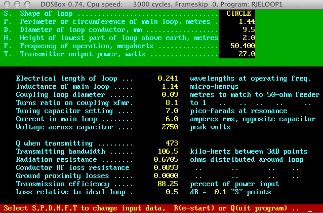
First step was to calculate a maximum efficiency loop on 50.4MHz without getting to low on the capacitor. The program used is RJELOOP1.exe:


7pf is too low. It turns out that RJELOOP1 overestimates the capacitor value a bit. The same thing happened with my 20/30/40m loop, which ended up being a 30/40m loop due to my 9-110pf capacitor being too high, or the loop being slightly too long. I made the same mistake here with the 6m loop. 4ft. would have been better. But back to the construction:

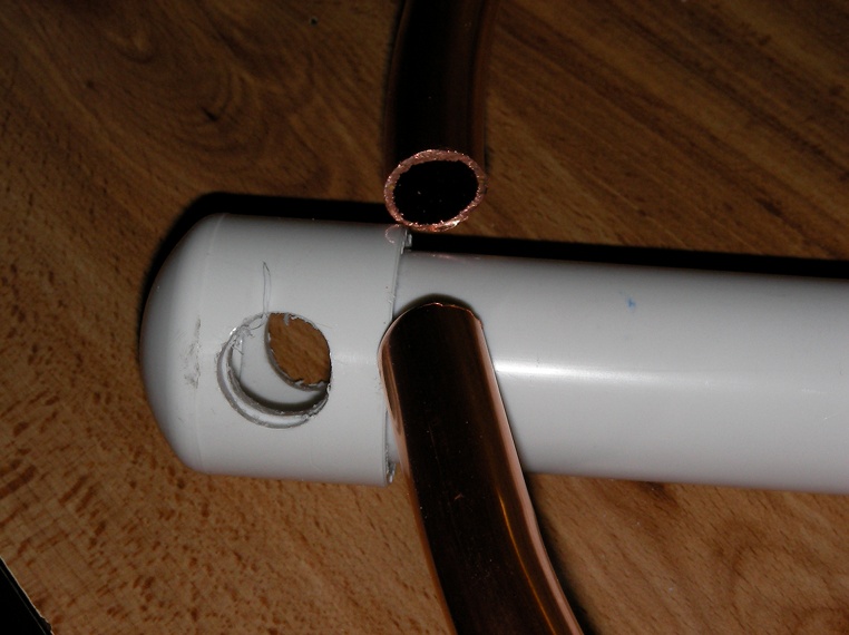
Here is the top cap and tube drilled using a drill press and 5/8 drill bit:


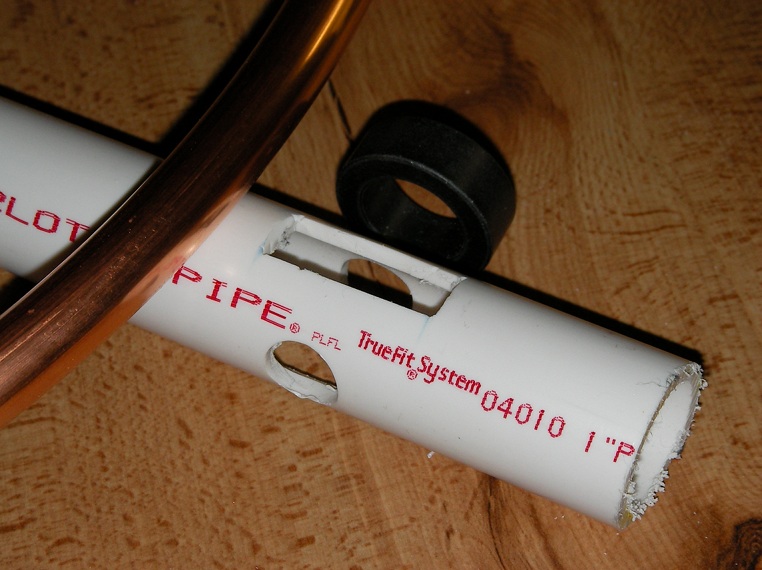
Below is the bottom where the loop will be fed, thus creating a horizontal polarization:


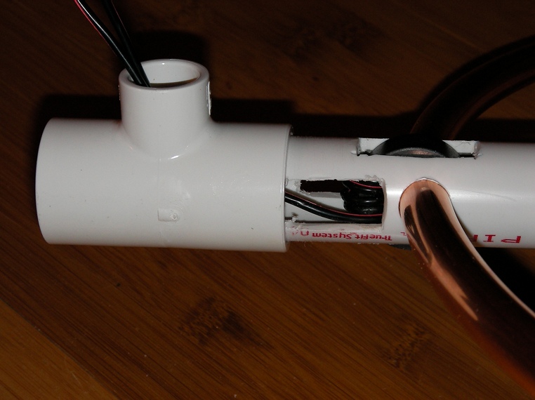
I had to open up another rectangle window below the round holes to allow for the wire to go through the toroid a few times. Here is the result:


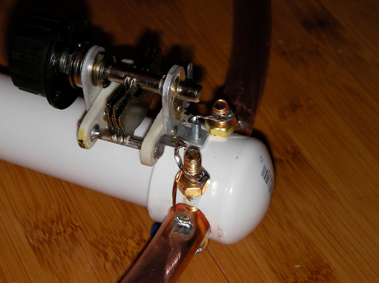
The capacitor is bolted on the PVC tube, through the end cap and the tube. A few washers on the bottom keep it level. I made slightly larger holes on the other side to get a screwdriver through.. I was not very happy about not being able to test the conductivity of the brass screws to copper tube connection (impossible to solder inside the PVC), so I used an external copper wire, which I soldered to the copper tube, then to the brass screws and the capacitor terminals.


Here is the completed loop with a 12" ruler for size:


I still need to put an SO-259 plug on the T coupler. Right now I used a binding post. At first I was able to thread five turns of wire through the toroid. As soon as I plugged it in, I new it worked! Though the capacitor plates barely overlap for peak band noise, which means my loop is a tad too long. It is fine, because the highest frequency it will be used on is 50.4MHz AM or below on SSB. SWR looked like 2.5:1, which is of course too high. I used a smaller feeding wire and managed to thread 7 turns through (every time the wire goes through the toroid counts as a turn..). The SWR got down to 2.1:1. I need to experiment some more. The SWR should go down to at least 1.5:1. My big loop gets 1.3:1... Maybe adding a couple turns will do the trick..

The loop is of course not meant to be carried by hand, though some people do that. I think it's crazy and way too dangerous. Look at the top image, it says 2750V with 27W in! I plug in another piece of PVC tubing into the T to get it high off the ground and away from anyone's reach or head... At first I thought I would paint it, but I like the copper color and might just spray a coat of clear acrylic on it..

Here is the latest addition to my stables, and the reason for building the 6m magnetic loop:


Now if only someone would answer my calls!

Ya'll have a happy new year!

Gil.
#2610
Antennas / Re: A magnetic loop antenna for 40/30/20m.
December 25, 2012, 08:21:22 PM
This one:

http://www.ebay.com/itm/E-F-Johnson-split-air-variable-capacitor-large-2-section-part-number-152-504-3-/251202802177?pt=LH_DefaultDomain_0&hash=item3a7cda9201

For air variable capacitors, since they are only one turn, I wouldn't use one with a range of more than 100 or 150pF. Otherwise, tuning will be difficult. Mine is a 9-110pF and is hard to tune already. the slightest movement of the knob throws the SWR way off. Also get one that has at least a 2KV rating, and that probably limits you to 10W (to be calculated), prefer a 4KV model. If you go too low, it will arc as you increase power.
Look at the link I posted previously, Surplus Sales of Omaha, if I recall.. They have good ones, though a bit expensive. Snatch that one above, it's a good one.. You can also put in in parallel for more capacitance or use the two gangs separately.. Gives you more options..

Gil.