Gil.
Buy me a coffee: https://ko-fi.com/gilgsn
Paypal:
https://www.paypal.com/biz/fund?id=WEYR7GMA494QL
YouTube:
https://www.youtube.com/c/radioprepper
Twitch: https://www.twitch.tv/radioprepper
Shirt & Mug:
https://teespring.com/stores/radio-preppers
Patreon:
https://www.patreon.com/radioprepper
Odysee:
https://odysee.com/@RadioPrepper:d
Facebook:
https://www.facebook.com/groups/radiopreppers/
Thingiverse:
https://www.thingiverse.com/Radio_Prepper
Send Bitcoins to: bc1qc5jq4dxt7359sh80lkv9v8rlsgnh322hmn6xyc
This section allows you to view all posts made by this member. Note that you can only see posts made in areas you currently have access to.
Show posts MenuI must here explain what an Elecraft K1 is.. Though it sounds like some fighter plane name, it is a receiver/transmitter (a "transceiver") which transmits, and receives CW (Continuous Wave) Aka "Morse Code." It is very small, and covers up to four Ham radio bands. Mine has two, 40 (7Mhz) and 20 meter (14Mhz). The power output is fairly low (7 Watts), but that is sufficient to bounce your signal around the earth.. Imagine seeing a 7 Watts light bulb thousands of miles away! Somehow, it works. CW punches through further than "phone" (voice). The K1 is in a class of radios called "QRP," meaning low power, usually 5 to 10 Watts. It is only sold as a kit, so if you want one, you must build it, or find a used one.. I chose to build it..
I don't understand the fear about winding toroids. I find it very easy and relaxing; it hurts much less than it sounds. All you have to do is count how many times you thread a wire through a ferrite core. How easier can it be? Then, you burn the enamel off the leads with a lighter, clean them up with your snipping tool, and solder.. I was very exited that night about the project. I thought it would be a walk in the park.. Not quite..
The front panel was next. The only difficulty there was soldering the LCD display. Attaching the wires to the ten-turn potentiometer also required some dexterity. About wires.. There are very few in the K1 kit: The potentiometer lead wires, speaker wire, and one coax jumper on the back of the board, that's it. Everything else is connectors. I like that. Soldering wires is always a pain in the butt.
The RF board was the biggest and longest one to build. It took me from around 10-am on Saturday to about 2:30-am on Sunday to complete it! And it didn't work! In retrospect, I should have only completed the receiver part that day, leaving the transmitter for Sunday. When tired, your brain plays tricks on you, and you make mistakes. Everything went fine with the receiver. I heard static when I turned the K1 on, no smoke. After tuning the receiver and plugging-in a long wire, I was listening to CW on both bands. I was exhausted, but proceeded with the transmitter side. It was 9-pm already, eleven hours of looking at tiny components, placing and soldering them.. Then came the time to test voltages on the RF board. Nothing on U8! Shit! Excuse my French.. That wasn't good. I nevertheless plugged-in the filter board to test power output. Nothing.. Followed about an hour of tinkering, swearing, manual-reading, head scratching shenanigans, of which I remember almost nothing (I had been working on it for 15 hours straight). I rewound the bi-filar transformer, reheated solder pads both on the filter and RF boards, zilch! Then I gave up, and decided to complete the build for the heck of it, and call Elecraft in the morning. Yet, after putting the speaker in and closing the box, I tried again. Power on 40m! Not on 20.. Ah.. Back to it (2-am).. I think I transmitted without a dummy load and no antenna a couple times by the way, I was so tired. Anyway, I have no idea what did it, but after countless little troubleshooting steps, and more tuning of the filter board, I finally got output power on both bands. I packed it up and went to bed with a headache and slight twitching..
Comes Sunday morning, I had a working K1! The only peculiar thing left to investigate is some power fluctuation.. If I set the maximum output to 2 Watts, the watt meter shows 2W at first, but then slowly climbs to 2.8. I am guessing that the final transistor produces more gain as it warms up.. I even produced about 10W tuning the filter board before the output suddenly dropped! Weird.. After tuning the filter board on receive, things are a bit more stable, still with quite a power increase as transmit time increases.. It shouldn't occur producing CW though, as this was transmitting a continuous tone in tuning mode. We'll see..
I spent Sunday evening listening to CW outside, with a wire strung horizontally (20ft maybe) about five feet from the ground; the worst possible antenna. Still, it was easy to pick-up signals. I even heard a guy saying he was on a sailboat, and retired three years ago (I have a Morse decoder app on my iPod!).
The Elecraft K1 kit is of very high quality; much better than any other kit I have seen so far (five). Everything fits perfectly, nothing was missing. I even had much needed left-over screws (I spilled them all on the garage floor).. The box looks great, and the way the circuit boards are positioned and fastened is brilliant. I will order the automatic antenna tuner and add it in soon. For now though, I need to finish learning code, then I'll go for the General Ham license (CW is no longer required). The K1 was the right choice, at the right price. You get a lot for your money. It might not seem so when you buy the kit, but after building it, I find it very affordable.
To anyone contemplating building one, go for it! Build a couple kits first, like a Small-Wonder-Labs Rock-Mite, and a SOTA tuner from qrpkits.com, and you'll be well on your way. Moreover, you can test the Elecraft receiver with the Rock-Mite! Get 50ft. of wire from Home Depot for the SOTA tuner, and you'll be all set. Follow the manual EXACTLY. Don't skip ahead, read every line! Double-check everything. Most importantly, don't do what I did. That was stupid. Take your time. If you feel tired or stressed, stop, rest, and don't get back to it until much later. I was very lucky that I didn't fry anything. Not to mention the stress and lack of sleep.. Not a healthy way to spend a week-end..
In the mean time, like they say over there, "Everything is fine in the best of worlds." I am a happy, proud builder and owner of an Elecraft K1. The satisfaction of building something that complex with your own hands is priceless..
My goal with this Rock-Mite is two folds. First, it is a stepping stone to building an Elecraft K1, which I have just started, and second, it provides me with a small emergency radio for my bug-out bag.
I can't really compare the DC20B to the RockMite as far as performance is concerned, but building the Rock-Mite is easier, and there is no tuning required. The circuit board is slightly smaller. I replaced q6 with a 2sc799. R18=2.2 ohms for a little more power. The keyer is the Pico Keyer from http://www.hamgadgets.com.
I am very exited about building the K1. More on that later...
There is one peculiar thing about this radio, aside from all it's qualities, that is, you can't talk in it.. Morse code only! Also known as "CW" (continuous wave). So I am learning Morse code, and it is far from easy. Why bother? First, a Morse-only transceiver is much simpler and smaller than an SSB (voice) one. It draws less current, which becomes very important when operating on batteries. The K1 will happily work for days on eight AA batteries! For example, a Yaesu FT-817ND draws 450mA on receive. The K1 draws 55mA! More importantly, when propagation conditions are bad, a CW signal will punch through the ether when another mode won't. In an emergency, being heard might be a life-or-death condition. Even with no cell phone coverage and no satellites overhead, there is a good chance the K1 will be heard somewhere, even thousands of miles away. Yes, thousands of miles directly, on eight AA batteries! What else can do that? It doesn't mean I won't take my cell phone or a Spot when hiking far from civilization. However, cell phone coverage is spotty in the North West, and with the Spot, you can't specify the type of emergency, and can only use it for dire situations. If I need anti-venom after a snake bite, it won't do me any good to get picked-up by a helicopter if they don't have the serum with them.. A radio allows you to call for a specific kind of help. Like any other gear, if it is too heavy or too big, you will most likely not take it with you. Light and small is better when you need to carry it on your back.
My plans are to first complete the 20/40m model with no add-ons. Then, I will build the built-in antenna tuner. This option allows you to use a random wire as an antenna without risking frying the transmitter. If you lost your antenna and all you can find is a length of barb wire, the tuner can save your bacon. Just hang it up a tree, press the tuner button, and seconds later, if you're lucky, you will be having a conversation. I might add a noise blanker later.. One item I decided against is the built-in battery pack. You can't charge the batteries while they are inside the case, so what's the point? I heard it is a flimsy add-on anyway. I don't think I'll need more than two bands, but time will tell. The antenna I chose is the Par EF-10/20/40 MkII end-fed dipole. Also on my wish list is a solar panel (PowerFilm AA Battery Solar Panel Charger) to charge those AA rechargeable batteries. For EMP protection, I decided to get some TechProtect Faraday bags.
I will document the build and post it. Average build time is about thirty hours, but I am pretty fast with a soldering iron. I will start next week-end (June 9th), stay tuned for the article, and maybe a video. Hopefully by then I will have learned a few more letters of Morse!
The circuit board it small: 3.5"x2.5". All the components come with the kit, with the exception of plugs needed to mount the PCB in a box. Actually, the kit was missing an integrated circuit socket (I found one at Radio Shack), and had two extra transistors..
It had been a long time (27 years) since I had finished electronics school. I had never soldered on a double-sided circuit board, but it turned out to be fairly easy. I just made sure I had a nice solder joint on both sides. The resistors went in first, then diodes, and so on, mounting the shortest components first, finishing with the talents. This way, you can use a piece of foam to press the components side onto it while you solder on the other side. This keeps the components near the board. One exception is the transistors. You don't want to overheat them, so it is better to mount them a little further out. The final output transistor is not put in until the kit is finished and tuned. Transmitting without a tuned antenna could destroy that component. Winding the coils was a pain. You need to make sure you count the turns carefully. One turn is every time the wire goes through the center. The parts are so small, I needed to wear reading glasses!
When all the components were in, I cut off the plug from old headphones and soldered them in. I also soldered a long wire as an antenna to test reception. It worked! I did hear faint morse code and SSB voices when tuning. The oscillator frequency however seems to be wrong: 14,063.2 Mhz instead of 14,060. I am not sure if there is a problem with the frequency counter, or I am that far off. The morse code keyed works too, so I have a working radio, except for the output frequency. I will need to find someone with an HF ham radio to check my tuning. I am investigating a way to fix the frequency problem and measure it accurately for sure. My progress will be posted here soon, as well as the mounting of the project in a box. Now I just need to learn morse code; darn, why didn't I think of that?
Update (May 27th): I think I am going to ditch the DC20B. I have a box for it, and should complete the build, but after that, it's going away. I can't get it on frequency, and I am not the only one... The Rock-Mite kit should arrive this week. I can't wait to build it. Look for the article!
Update (May 30th): Well, I gave it one last try.. Changed C36 to a 100pF, and C29 to 47pF. It worked! Now I get 14,059.72 on transmit. Receive goes from 14,060.16 to 14,060.32, a perfect 600Hz offset. The problem is the receiver, which has no selectivity. I receive Chinese, French and Spanish commercial radio stations, but little, faint CW signals. Maybe the problem comes from the wire I use as an antenna, which isn't tuned. I will try a tuned dipole during the day and see if I can get clear CW (morse code). I boxed up the DC20B in a nice Hammond cast aluminum box. I made a hole in the cover to tune CT1 and glued a piece of coax outer insulation so that I can't touch anything with my screwdriver upon insertion.. The box is a little big, but it looks good and as though it would survive being run over by a semi-truck.. I might make another hole for access to CT2 and add an RCA plug for a frequency counter (for tuning).
Still waiting for the Rock-Mite (shipped today).
Elecraft K1 arrives tomorrow (June 7th).
Most people know the Citizen Band through movies like "Smokey and The Bandit," "Convoy" and others, mostly involving truckers. That is just one side of the coin. The other side are the operators trying to cover the greatest distance possible, and activity called "DX."
CB has a good thing going for itself right now, that is the peak of solar cycle 24. Propagation is going to be very good for probably another couple years. Radio waves in the 11m (27Mhz) band do bounce off the ionosphere when conditions are right. SSB being excellent at receiving weak signals, you have a very good chance to skip pretty far.
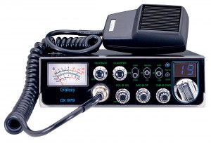
The Galaxy is cheaply made (compared to a Yaesu HAM radio of similar price). The buttons on the front panel are "chromed" plastic and look cheesy. The whole radio looks and feels cheap. I even had a very hard time putting in the mounting bracket screws. I had to tighten them with a pair of pliers and was lucky not to strip any thread. Looking inside the box gave me the same feeling. I like the big meter and the fact that you can dim the blue LEDs.
I connected the transceiver to my Solarcon Max2000, a 24ft. antenna mounted about 15ft off the ground, surrounded by trees, and an Astron power supply. Good thinking from Galaxy for putting the microphone plug on the front panel by the way, which I plugged in, then turned the volume knob to ON. It worked! I shouldn't be so negative, since I suspect that most CB radio manufacturers produce the same lever of "quality." I tuned to 38LSB and listened, playing with the clarifier whenever I heard someone calling DX.
[tip]The clarifier is the knob that turns the "Donald Duck" voices you hear on SSB into something you can understand.[/tip]
If you are a safe cracker by trade, you won't have any trouble with the clarifier on the 979. It takes that kind of finger dexterity to operate the darn thing. Before you have a caller "clarified," he is usually done talking.. Aggravating.. The range on the clarifier is too broad. My old President Jackson has a much better clarifier, but of course, that radio has acquired a quasi legendary status in the CB world. With a little practice, you get better at it, but geez!
Compared to HAM transceivers, CBs are noisy... I plan on replacing a few diodes with Schottky Barrier Diodes, and replace an RF amp transistor with a 2sc2999, High Gain, Low Noise model. The procedure is described here; part are on the way (about $1.60!).
I remembered that I should check the SWR before transmitting, which was a perfect opportunity to test the inboard SWR meter. I also plugged in a Workman el-cheapo meter on the antenna output. They did not agree with each other! The Galaxy SWR meter barely moved while the workman showed 1:1.8! I tuned the antenna and got down to 1.6 (probably all those trees..). Oh well. Just keep an eye on the SWR warning LED.. It works (I had a short in one plug); the SWR meter also jumped up. It might not be the most sensitive SWR meter, but it will let you know when you risk frying your final transistors.
It was getting late and the band was dying down when I heard "476" calling. He did not say where he was from, but I could hear him very well, good audio and a signal of 7. I expected him to be within fifty miles of me. I asked him about his location and he said "Jamaica!" I had a low signal but good audio (mike gain turned all the way up). Not bad for a $140 piece of gear. The antenna is everything, mind you, and the IMax2000 did it's part. The Galaxy... I hadn't wasted my money..
The Galaxy DX 979 won't win manufacturing quality contests. It does however work well. For the price, you can buy two and box one up in an ammo can for EMP protection. It is a small price for never being entirely cut off from the rest of the world.
Total length very-top to very-bottom is 58". Width center-to-center is 2". Gap is about 1-3/4". See the Ham-Universe articles (1 & 2) for exact measurements.
It is easy to calculate dimensions for other frequencies:
The gap is taken off the 1/4 wave element...
The PVC Ts need to be reamed with a 5/8" drill bit so that the copper tubing can go through. I used a bit of WD40 to slide them down. Between the two Ts, I epoxied a 1" piece of 1/2" plastic tubing. There is one "H" PVC support assembly on the top portion and one on the lower portion, right next to the end cap.
I am not sure that using a plastic electrical junction box was a good idea for the feed point. Since I have not received my SO-239 socket yet, I must hold off on the electrical connection. My concern is that soldering will be difficult without burning the plastic box. I might have to use sheet-metal screws. Tunig might not be easy either, since the best SWR is obtained by moving the feed point up and down, between 3 and 4" from the very-bottom. Maybe I should have used PVC Ts, like for the two support "H" assemblies. They can be split in half, then the coax soldered after finding the best feed point. Once epoxied, it would look fine. I do like the look of my electrical box though, and if it works fine, I will be happy with the results.
Total building time was about an hour. Everything came from the hardware store, except the SO-239 connector. Soldering turned out to be pretty easy. I sanded the parts and used flux paste before heating up the assembled parts with a torch. Once the parts are hot enough, you put the solder on, which flows in the joint, following the flux. Cost could have been as low as $30, but I spent about twice that much, not counting tools (hacksaw, drill bit, epoxy, solder), which you might have already. If you are starting "empty handed," plan on $100. While it can cost more than a factory-made antenna, you get the satisfaction of building something yourself, which might be actually sturdier than a store-bought model.
Stay tuned for the finishing touches (painting), electrical connection and reception testing.
Thanks to Richard KE5FXU SK at hamuniverse.com for the article!
Update, April 11th:
Finally, I got my SO-239 plug. Drilling the PVC box was easy. I didn't even use my drill press. It only took me a few minutes by hand! Holes are one 5/8" in the middle, and four 1/8" around. I drilled in the middle of the lid, hoping I would have enough leeway to adjust the SWR by moving the contact in the box along the tube. First, as I suspected, I could not get the tube hot enough to solder the center of the coax to the copper tube using my 30w soldering iron. I solved the problem by heating up the tube with a Zippo under it while I soldered on top! It worked really well. I did the same to put soldering points in the box, every quarter inch or so. The zippo was placed an inch from the box. I was worried about melting it, but these electrical boxes are pretty heat-resistant. Sorry about picture quality:
It's a bit ugly, but inside the box anyway..
Reception works great. I was able to listen to a conversation tonight on a distant repeater that I simply could not hear with the HT rubber antenna. I get three extra signal bars with the Slim Jim. I got a cheap VHF/UHF digital SWR meter from Hong-Kong, which seems to work fine, but for the connectors which are of "N" type.
Update, May 1st:
I painted the antenna sort of a flat olive-drab color for stealth. I can easily hoist it up a tree and it blends in very well. SWR varies from 2.4:1 on the lower part of the band, to 1.8:1 around 146Mhz, and remains around 1.4:1-1.5:1 from 146.5 up. I used a ferrite RF choke kit from Palomar Engineers (photo below), which got the SWR down to 1.36:1 around 147.5Mhz. I much prefer the ferrite choke to the coax balun type, which looks ugly and wastes cable.